This post is part of a series covering a study performed by Stratasys Direct Manufacturing and the University of Texas, Austin. Read part one on wall thicknesses or download the full white paper.
To achieve a hole using 3D printing, there’s no drilling required. As with all 3D printing features, holes are built directly into a part in a layer additive process. When designing holes meant to be built with Selective Laser Sintering (SLS) 3D printing, there are two factors to consider: Diameter versus wall thickness and the proximity of the hole(s) to other design features including the edge of the part. To determine an optimal range of hole diameters, distance and resolvability for both large and small holes, the University of Texas created a stair stepped design with 21 holes with diameters starting at 0.125 mm and ending at 4 mm. The results of how well these diameters resolved will help you design a successful SLS part.
Diameter
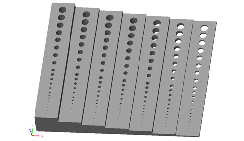
The stair stepped design (shown below) incorporates seven different wall thicknesses with holes through each stair starting at diameters of 0.125mm and ending as large as 4 mm. The largest diameter created a better gauge for marking tolerance compared to the CAD model. This design was built in both vertical and horizontal orientations, where orientation is determined by the relation to each Z-axis cross-section.
Our tests revealed that hole diameters smaller than 1.5 mm won’t actualize through SLS printing. We recommend keeping holes larger than 1.5 mm when possible, and to build smaller holes in a vertical orientation. Vertical orientations proved to meet tighter tolerances, which in turn maximizes resolution for hole features. With regards to wall thicknesses and how they relate to hole diameter, it is advisable to keep wall thicknesses surrounding holes around 3.0 mm to protect against feature deformation. Our table below demonstrates the pass fail matrices for both vertically and horizontally oriented holes.
Proximity
As we mentioned above, giving holes 3.0 mm wall thicknesses provides good stability for capturing its features. In relation to structural support, some distance between holes and other features or the wall of the design itself is required to ensure the hole will completely form. Holes placed too close to the edge of a wall will result in a failure to resolve. We tested hole proximity using the design below, which had a range of hole diameters, from 2.5 mm in diameter to 10 mm in diameter, and tested their distance from the wall. Based on diameter, distance to the wall, and feature orientation, we were able to determine optimal distances for holes depending on their size.
When determining the distance between holes and other features, optimal proximity is largely determined by hole diameter. A good rule of thumb is to keep a 1.0 – 1.05 mm distance between the hole and other features when the hole diameter is between 8.75 – 10 mm. Smaller diameters, between 5 – 7.5 mm, should be around an 0.85 – 0.90 mm distance between other features and part edges. We recommend building holes via a vertical orientation for best results. Below, we’ve demonstrated the pass/fail matrices for hole diameter to proximity results.
If you found these design tips helpful, be sure to check out our full white paper on Selective Laser Sintering. “An Insider’s Guide to Selective Laser Sintering” is a comprehensive white paper for the designer ready to become an expert in 3D printing.


